Applications
Manual Metal Arc Welding can be used for both joining and coating applications, whether for the protective coating of new parts or the build-up and repair of parts.
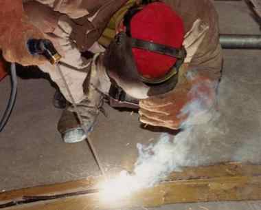
Manual Metal Arc Welding
Stick electrodes
During welding the metal core wire melts to create the welding deposit. The flux coating covers the deposit and protects it from oxidation.
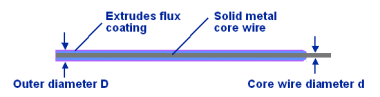
Stick electrode
The flux coating includes a variety of constituent materials:
- for shielding of the weld zone
- for optimum arc stability
- for uniform fusion of the alloy
- for control of the process of deposit solidification.
The diameter of a coated electrode is in fact the diameter of its metal core.
Performance of a stick electrode for maintenance and repair welding
- Weldability with a.c. or d.c. and low O.C.V.
- Outside welding
- Easy to use - Mobility
- Striking and restriking ease
- Arc stability and low heat input
- Metal transfer mode
- Fluidity of the molten pool
- Positional weldability
- Slag removal
- Bead shape and appearance
- Gap bridging capabilities
Characteristics of the different types of flux coatings
| Code |
|
Covering types |
|
Characteristics |
|
|
|
|
|
| R |
|
Rutile type / components deriving from titanium oxide: medium coated |
|
Good weldability, medium penetration, suitable in vertical-up position. |
| RR |
|
Rutile type / components deriving from titanium oxide: heavy coated: D / d > 1.55 |
|
Use is restricted to horizontal welding position |
| B |
|
Basic type containing large quantities of calcium or other basic carbonates and fluorspar, usually heavy coated |
|
The deposited metal is highly resistant to cracking: suitable for welding heavy sections. Welding in all positions. Basic electrodes must be very dry. |
| C |
|
Cellulosic type containing a large quantity of combustible organic substances. |
|
Highly penetrating arc. Welding in all positions. Spatter losses are fairly large. Typical application: pipeline welding. |
Storage of coated stick electrodes
Electrodes need to be stored in a very dry place (constant temperature of 15° to 21°C).
Especially, basic electrodes should always be stored in a dry atmosphere (constant temperature of 15° to 28°C).
Damage through handling and storage will cause uneven burnoff of the flux coating and produce defective welds.
Drying of basic coated stick electrodes before use
see manufacturer's instructions
Preparation of base materials
- For optimum results worn components should be cleaned and properly prepared prior to welding.
- Components which have been in service may exhibit damaged and / or fatigued areas. Fatigue cracks will more likely contain other contaminants.
- Damaged areas should be dressed by grinding or gouging.
- It is important that all contaminants be removed before welding.
- Sharp edges can be prepared by removing these areas to form a radius (this will reduce overheating and uncontrolled dilution).
Welding parameters
Parameter setting
- The current setting for any electrode diameter influences the fusion rate (deposition rate) and the penetration
(see manufacturer's instructions
- The voltage varies with the arc length:
- Long arc: higher voltage
- Short arc: low voltage
- For direct current (d.c.), the correct polarity has to be chosen (see marking on the electrode)
In manual electrode welding, the welding speed is a parameter which is difficult to measure exactly. In practice, the length of the weld bead is often considered as the yardstick for welding speed. But this can vary from one kind of electrode to another.
Amperage
If amperage is too high the following problems may arise:
- electrode may overheat, possibly damaging the flux coating
- oversize of the molten pool
- insufficiently shielded pool, resulting in a porous weld
- large crater at the end of weld with porosity and crack formation possible
- undercutting
- spattering
- slag hard to remove
- excessive penetration in welded joints
If amperage is too low the following problems may arise:
- difficulty in striking the arc
- intermittent arc
- discontinuous fusion of flux coating due to partial arc
- poor bonding and slag inclusions
- porosity
Welding speed
If the welding speed is too high the following problems may arise:
- the weld will be inadequately protected by slag
- incomplete fusion
- slag inclusions and porosity
- in the weld joints: insufficient penetration
If the welding speed is too low the following problems may arise:
- slag inclusion
- in the weld joint: excessive penetration
Arc length
If the arc is too short the following problem may arise:
If the arc is too long the following problems may arise:
- the arc breaks
- porosities and inclusions due to ingress of air
- undercutting
- incomplete fusion
- spattering
Shrinkage
Transverse shrinkage
Procedure:
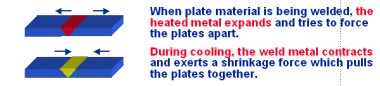
Transverse shrinkage
Transverse shrinkage causes internal stresses and plastic deformation in the heat affected area.
In certain cases the resulting stresses will also cause cracking during welding, cooling or in subsequent service.
How to control transverse shrinkage:
- Ensure that plates are not misaligned
- Pre-setting before tack welding
- Weld metal should kept to a minimum consistent with requirements
- Stringer beads
- Minimum heat input during welding
Longitudinal shrinkage
Procedure:
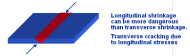
Longitudinal shrinkage
Transverse cracking due to longitudinal stresses or longitudinal cracking due to shear stresses can be the results. The cracks can propagate at high velocity.
How to control longitudinal shrinkage:
By following the correct welding sequences !
For further information, on-site training, technical advise or project management, please do not hesitate to
contact us.
|