Applications
MIG / MAG Processes can be used for both joining and coating applications, whether for the protective coating
of new parts or the build-up and repair of parts.
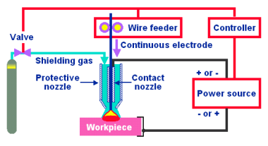
MIG / MAG welding process
Continuous electrodes
The continuous electrode can be solid relying on gas shielding to provide both good metal transfer
and protection of the molten pool.
Alternatively, a metal or flux cored continuous wire is available. Both relie on additional shielding
gas similar to solid wire.
Storage of continuous electrodes
In particular, care must be taken in the storing of continuous electrodes to protect them from contamination,
oxidation, rust, etc., causing feeding difficulties through the lining, and other harmful effects including
increased electrical resistance at the torch contact tube.
Damage through rough handling and inadequate storage may produce poor electrode feed, current fluctuations,
control problems, oxide inclusions or porous deposits.
Preparation of base materials
- For optimum results worn components should be cleaned and properly prepared prior to welding.
- Components which have been in service may exhibit damaged and / or fatigued areas. Fatigue cracks will more likely
contain other contaminants.
- Damaged areas should be dressed by grinding or gouging.
- It is important that all contaminants be removed before welding.
- Sharp edges can be prepared by removing these areas to form a radius (this will
reduce overheating and uncontrolled dilution).
Cable-gun unit
The MIG / MAG torch or gun unit includes the power lead, the shielding gas feedline,
possibly the coolant, and the consumable.
The welding current is transferred to the electrode by a sliding contact, in the contact tip. Up
to 300 A the torch is normally gas-cooled. being water-cooled beyond that range.
Both the shielding gas nozzle and the contact tip should be cleaned regularly and protected
using anti-spatter compound.
Shielding gas
The choice of shielding gas will affect all the following:
- Temperature distribution in the arc
- Arc characteristic and droplet transfer
- Arc stability
- Arc shape
- Depth of penetration
- Deposit geometry
- Risk of porosity
- Mechanical properties
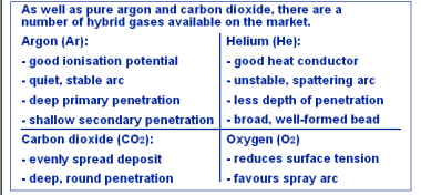
Influence of the various constituent gases
Parameter setting
Short arc (dip transfer) and spray arc (spray transfer):
- Select the welding voltage on the welding source
- Regulate the wire speed via the wire speed potentiometer adjustable from 0 to 10, 15, 20 or more m/min.
The motor of the MIG / MAG wire-feeder is powered by an adjustable voltage.
The speed is therefore adjustable but constant during welding.
The amperage adjustments necessary for stabilising the arc are made by the power source.
- Inductance for short arc welding:
The best dynamic is usually between two extremes.
- When inductance is too high, correct droplet formation is hindered.
- When inductance is too low: spatter may result.
- Inductance for spray arc welding:
The inductance is set to the minimum (zero), to achieve dynamic balance in the arc.
Pulsed arc:
- Select the parameters for pulsation voltage on the welding source
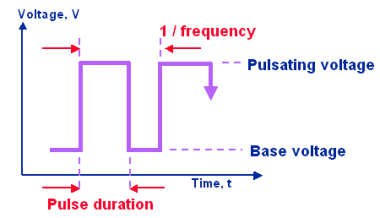
Pulsed arc: Parameters for pulsation voltage
- Base voltage is necessary for maintaining the arc during cold phase. Typical values: min. 10 V ( min 20 A )
- Pulse voltage controls the current pulsation. Higher pulsating voltage increases the heat input to the weld pool.
Typical values: max. 40 V ( max. 500 A )
- Pulse duration: A longer pulse duration increases the heat input, and also influences the diameter of
the droplets in formation. Typical values: 1 to 15 ms.
- Frequency: Higher frequency increases the heat input, as well as the number of droplets transferred per unit of time.
Typical values: 30 to 300 Hz.
- Wire feed speed: Higher wire feed speed has a particular influence on the deposition speed. Higher feed speed requires
higher pulse frequency.
Regulate the wire speed via the wire speed potentiometer adjustable from 0 to 10, 15, 20 or more m/min.
The motor of the MIG / MAG wire-feeder is powered by an adjustable voltage.
The speed is therefore adjustable but constant during welding.
The amperage adjustments necessary for stabilising the arc are made by the power source.
- The inductance is set to the minimum (zero).
Perfect formation of the pulses requires limiting the inductance of the electrical circuit. Make sure never to coil the earthing cable or the cable assembly connecting the power source and the wire feeder.
The earthing cable must lie parallel to the cable assembly, with a minimum distance between the two.
For further information, on-site training, technical advise or project management, please do not hesitate to
contact us.
|